Kiln Specifications
TYPE
Model
USA-27
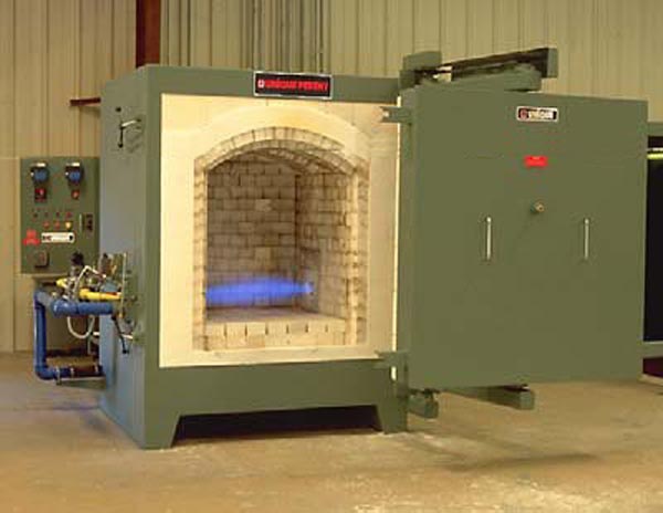
Front Loaded Chamber Kiln
FUNCTION
Technical Ceramic Products
KILN CAPACITY
27 Cubic Feet
SETTING DIMENSIONS
Width - 36 inches
Depth - 36 inches
Height - 36 inches
KILN LINING
9.0" of 3300ºF bubble alumina refractory
4.5" of 2600ºF insulating firebrick
1.5" of 1900ºF block insulation
15.0" Total Wall Thickness
TYPE BURNERS
High velocity, high turn-down, nozzle mix
NUMBER OF BURNERS
Two (2)
OPERATING TEMPERATURE
1650ºC
FIRING CYCLE
Various
FUEL
Natural
gas
KILN RATING
3,000,000 Btu/Hr.
TEMPERATURE CONTROL ZONES
One (1)
ELECTRICAL SERVICE
480V, 3ph, 60Hz
GAS SUPPLY
3
psi
DRAWING NUMBER
KI0575
SECTION 3
Kiln Description - Mechanical
Steel Structure
The outer shell will consist of structural steel
members
combined with heavy gauge 3/16" plate, welded together
to form a strong, stiff integral unit. Structural
tubing is
utilized in the base design to provide combustion air
for the
burners. Combustion airflow helps keep the base cool
at
high kiln temperatures, contributing to long life. The
entire
kiln is mounted on heavy-duty structural support legs.
All
exposed metal surfaces will be painted with high
temperature paint.
A COOL SKIN
TM
coated steel sheet will be
attached to the
Kiln door and side walls. This combination radiation
and
convective shielding provides a cooler work
environment in
front of the kiln by reducing the outer skin
temperature.
Refractory Lining
The kiln walls are lined with a total of fifteen
inches (15") of high quality refractories. The composite
wall design is as follows:
•
Nine inches
(9") of 3300ºF bubble alumina refractory brick
•
Four and one-
half inches (4.5") of 2600ºF insulating firebrick
•
One and
one-half inches (1.5") of 1900ºF calcium silicate insulating block
Anchoring bricks secure the lining to the steel shell
by means of specially designed
AFloating@
alloy
anchors. Generously sized expansion joints help to
compensate for the tendency of the hot face
refractories to grow over time. The kiln hearth
brickwork is composed of high quality refractories,
properly anchored, to minimize maintenance.
The kiln roof is a turned arch design with a nine inch
(9") hot face of wedge shaped 3300ºF bubble
alumina refractory bricks, covered with layers of
2600ºF fiber blanket.
Door Arrangement
The door of the "USA" kiln is a refractory lined, full
opening double hinged, non-sag door fabricated
of structure steel with heavy duty, positive action
door clamps. The full opening door allows the
operator to stand directly adjacent to the setting
deck when loading and unloading product. A port is
located in the center of the door to observe the
product setting area or to sight with an optical
pyrometer.
Exhaust Outlet
The "USA" Front Loaded Chamber Kiln is an updraft
design, where exhaust gases are discharged
through an opening in the Kiln roof. Refractory slabs
are positioned above the roof slot to minimize
heat radiation out of this exhaust slot, thereby
conserving fuel and improving temperature uniformity.
SECTION 4
Combustion System
NFPA Standards
The combustion system will be built to meet NFPA
standards in effect at the time this proposal is
submitted. The complete combustion system has
consciously been designed to meet all significant
and well-defined standards that are recognized in the
United States.
Combustion Components
This kiln is heated with two (2) specially modified
high turndown burners. Burners are positioned to
fire horizontally in the space provided beneath the
product setting deck. The high velocity burners
entrain and circulate kiln gases as they pass around
and through the product setting, creating
excellent circulation and temperature uniformity.
Both burners are grouped into a single temperature
control zone. The control thermocouple is
carefully positioned within the kiln chamber to assure
reliable repeatability. This system
automatically compensates for variations in product
settings from cycle to cycle thereby providing
the best possible temperature control.
Each burner is spark ignited and equipped with a
shutoff valve, solenoid valve, and fuel and air
balancing valves. In addition, each burner has an
independent fuel metering orifice to insure simple
and accurate setup of the fuel/air ratio. For the
ultimate control, each burner has its own control
regulator. An automatically controlled impulse line
manages the fuel flow to the burners to maintain
accurate temperature control in the kiln throughout
the heating portion of the cycle.
The air supply blower, which is floor mounted behind
the kiln has sufficient capacity to provide the
appropriate combustion air supply as well as
additional air for cooling. A butterfly valve in the main
combustion air supply line is automatically regulated
to control the cooling portion of the firing cycle.
SECTION 5
Controls
Fuel Supervision
Pressure switches will be applied to the combustion
air source and fuel train to insure that the
appropriate values are maintained. A Modular Gas Train
which includes the main pressure
regulator plus required pressure switches is attached
to the back of the kiln structure. All of these
devices work in concert to shut down the fuel delivery
in the event of a problem.
Each burner is equipped with UV flame sensors that
detect the presence of flame. This device acts
to shut down the fuel to an individual burner in the
case of flame failure.
Temperature Control
Control functions are through a Honeywell Model
DCP-100 Programmer and a Honeywell Model
UDC-3300 Controller. These instruments provide the
following control functions:
•
Time/Temperature set point programming of the kiln temperature with
fuel only control.
•
Programmed
conversion to controlled cooling followed by regulation of the
combustion
air input to control the cooling curve.
All controls are mounted in a free standing control
console, ergonomically arranged for simple and
logical operations. Appropriate alarms will be
supplied for flame failure at any burner, loss of air,
fuel, and/or over temperature.
A dual element type-B thermocouple is supplied. One
element is used for monitoring and control of
the process temperature and the second is
independently wired to the over temperature controller
for automatic Kiln shutdown in the event of over
temperature.
Automatic Fuel Shutoff
This system includes an adjustable timer in the
microprocessor programmer to be set for the time
the fuel is to be shut off. After the fuel is shut
off, the combustion air blower remains in operation to
provide cooling. A second adjustable timer in the
programmer is set for the total length of the cycle
time, and shuts down the entire kiln at the end of the
program.
Over-Temperature Control
This system senses the temperature in the kiln with a
dedicated thermocouple mounted just below
the roof of the kiln. The thermocouple is connected to
a separate on-off over temperature controller
mounted in the control console.
The kiln over temperature set-point is programmed into
the controller at approximately 15º C above
the maximum soak temperature. If, at any time, the
temperature reaches this preset temperature,
an alarm is energized notifying personnel of the
over-temperature condition. If the situation is not
corrected within a preset period of time, then the
kiln is shut down.